


MDFA Pull Test Standard

STANDARD MDFA-101-95
TEST METHOD FOR DETERMINING BREAKAWAY FORCE OF A MAGNET
DISCLAIMER: This test method was developed by representative members of the Magnet Distributor and Fabricators Association (MDFA) to provide their opinion and guidance on a testing method to determine the breakaway force of a magnet. This document contains advisory information only and is published as a public service by MDFA. MDFA DISCLAIMS ALL LIABILITY OF ANY KIND FOR THE USE, APPLICATION OR ADAPTATION OF MATERIAL PUBLISHED IN THIS DOCUMENT.
Magnet Distributors and Fabricators Association
11 S. LaSalle Street 0 Chicago, Illinois 60603 0 312-201-0101
Copyright 1995 by
Magnet Distributors & Fabricators Association
All Rights Reserved
Contents
- 1.0 Scope
- 2.0 Terminology and Definitions
- 3.0 Summary of Test Method
- 4.0 Significance and Use
- 5.0 Apparatus
- 6.0 Hazards
- 7.0 Preparation
- 8.0 Calibration
- 9.0 Procedure
- 10. Calculation of Results
- 11. Report
- 12. Precision and Bias
1.0 Scope
1.1 This test method addresses the measurement of the normal force required to detach a magnet from a work load surface. This test method covers both electro and permanent magnets.
1.2 This test method may involve operations which require the use of appropriate precautions, and does not purport to address all of the safety-related matters associated with its use. It is the responsibility of the user of this standard to establish the appropriate safety practices and determine the applicability of regulatory limitations prior to use.
1.3 Units of Measure. Measured values may be recorded in pounds, kilograms, or newtons.
2.0 Terminology and Definitions
2.1 Air Gap: Any gap between the magnet-working surface and the work load surface that is occupied by a non-magnetic material.
2.2 Breakaway Force: The force required to detach a magnet from a work load surface when the force is applied normal to the work load surface and through the center of force of the magnet. In most cases, magnet designs are symmetrical, and the center of force will coincide with the center of gravity of the magnet. In a case where the magnet configura-tion is highly asymmetrical and the center of gravity does not coincide with the center of force, a preliminary test should be preformed to determine the center of force. The pulling force shall only be applied through this center of force.
2.3 Gap-Force Curve: A curve which shows the relationship of breakaway force of a magnet with a varying air gap on a common surface.
2.4 Flux Density: A term describing the number of lines of magnetic flux per unit area emanating from a magnet at a location external to the magnet.
2.5 Magnet: As referred to in this document, a magnet may be a single permanent magnet, a magnet assembly consisting of one or more permanent magnets and other components, an electromagnet, or a permanent-electromagnet combination system.
2.6 Pole Pieces: Ferromagnetic components (such as iron) of a magnetic assembly which transfer magnetic flux to a workload and which may function as the working surface of the magnet.
2.7 Saturation: (As defined here relates to a ferromagnetic material used in conjunction with a magnet.) A condition in which a ferromagnetic material is unable, as an externally applied magnetic field is increased, to conduct any additional lines of magnetic flux. This capac-ity varies according to the permeability of the material.
2.8 Surface Roughness: A measure of the smoothness of a surface, measured in micro inches or micrometers.
2.9 Test Plate: A mild steel plate of specified composition, surface roughness, and flatness. The required thickness shall be such that the plate remains unsaturated by the magnetic flux of the test magnet. The test plate is used to test the breakaway force of a magnet.
2.10 Under-the-hook: Signifies applications in which magnets are used to lift and transfer large or heavy workloads.
2.11 Working Surface: That surface of the magnet that is used to perform the work.
2.12 Workload: The object to be held or lifted by the magnet.
3.0 Summary of Test Method
The magnet breakaway force is determined from the measurement of the holding force of a magnet against a test plate. A gradually increasing load is applied in a direction normal to the workload surface and through the center of force of the magnet. The load that separates the magnet form the test plate is defined as the breakaway force.
4.0 Significance and Use
4.1 The breakaway force capability of any magnet is dependent on various factors, i.e.:
- Magnet material and shape
- Pole material and configuration
- Workload mass, composition, roughness, and flatness
- Air gap between magnet and workload
- Temperature of magnet
Calculations may be performed to estimate the breakaway force of a particular magnetic configuration. This MDFA test method will provide the format required to verify, through testing, the actual breakaway force of a magnet.
4.2 In order to specify the breakaway force characteristics of a magnet, the breakaway test may be performed at a number of different air gaps. The resulting gap versus force curve provides a more complete magnetic characteristic of the material in practical application. This data is significant in the design and use of magnet systems that work through air gaps, as well as for determining the effects of magnetic gaps which may occur over time. Air gaps may be introduced by design, by changes in the surface roughness, by the formation of rust on either the workload surface or the magnet-working surface, or by the introduction of paints or other coatings between the magnet and the workload. The breakaway force of a magnet decays exponentially as the air gap is increased. The exact severity of the exponential decay with distance depends on the magnet design.
4.3 Variations in breakaway force of otherwise identical magnets may be produced by:
4.3.1 Variations in the magnetic properties of permanent magnet components. This type of variation may considerably alter breakaway forces based on the proportionality of the force to the square of the magnetic flux produced by the magnet.
4.3.2 Surface roughness of the magnet-working surface and of the workload surface.
4.3.3 Composition and mass of workload.
4.3.4 Temperature of the magnet. The magnetic properties of all magnet materials are reduced at elevated temperatures. The magnetic properties of different magnet materials decay at different rates and, if elevated temperatures are a concern to the user, this effect should be evaluated. Note in particular that electromagnets, which conduct electric current through a coil, will generate heat thereby varying the coil resistance and affecting the magnetic capabilities.
4.3.5 Variations in test equipment and/or execution of test by operator.
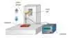
5.0 Apparatus
5.1 A test plate made of 1018 cold rolled steel, ASTM A794 (current edition), with a surface area large enough for the magnet-working surface to make 100% contact. A surface roughness of 63 micro inches, and a flatness or 0.001 " over the contact surface is required. Plate thickness must be such as to absorb all lines of magnetic flux emanating from the magnet, i.e., remains unsaturated.
5.2 Gauss meter to check for saturation of test plate.
5.3 Surface roughness and flatness measuring devices.
5.4 Fixtures to hold the magnet and the test plate evenly through the magnet center of force while a load is applied to separate the magnet from the test plate.
5.5 A method or device to provide a gradually increasing pulling or pushing force against the magnet and the test plate.
5.6 A device which provides a measure of the total force being exerted between the magnet and test plate.
5.7 A method for recording the peak force at which breakaway occurs.
Suggested apparatus for measuring breakaway force:
Test plate mounted on roller bearings to allow self-alignment so that load is applied to magnet through magnet's center of force. Load cell (strain gauge) that relies on resistance change with force applied. Resistance change leads to change in current flow, which can be measured. Output can be read by device calibrated to give results in appropriate units of measure. Output devices should, as a minimum, be able to retain peak readings. Many standard commercial devices are available.
6.0 Hazards
6.1 Precautions should be taken by the tester to ensure that when breakaway occurs the magnet and test plate do not move out of control causing injury or damage.
6.2 When lowering the magnet to the steel test surface, ensure that the magnet does not slam against the test surface by its attracting force. Some magnet materials are typically brittle and may crack with impact.
7.0 Preparation
7.1 Testing shall be conducted between 50 and 90 degrees Fahrenheit.
7.2 Verify surface roughness of the test plate to be 63 ± 5 micro inches, and flatness over contact area to be within 0.001".
7.3 Verify that the working surface of the magnet makes 100% contact with the test plate.
7.4 Verify that the load applied to the magnet is perpendicular to the plane of the magnet-working surface.
7.5 Verify that the test plate is not saturated by measuring the flux density on the surface of the test plate opposite to the surface the magnet is in contact with. For purposes of this test method, the flux density on this opposite surface shall be less than 5 Gauss.
8.0 Calibration
8.1 Any instrumentation to be used as specified in section 5.0 shall have proper calibration certification.
9.0 Procedure
9.1 Perform any calibration steps required for equipment.
9.2 Record ambient temperature.
9.3 Record surface roughness and flatness of contact surface of test plate.
9.4 Place the working surface of the magnet flat against the test plate. Verify that all working areas of the magnet are in complete contact with the test plate.
9.5 Record the flux density on the back surface of the test plate (as defined in 7.5 above).
9.6 Set up available apparatus to provide and measure breakaway force.
9.7 Verify that the load is applied through the center of force of the test plate/magnet assembly.
9.8 Adjust the force-measuring device to zero after set up is complete and prior to applying a force.
9.9 Apply a gradual pulling force to separate the magnet from the test plate. Continue to increase the load until the magnet separates from the test plate surface.
9.10 Record the value at which breakaway occurred.
Option (Reference 9.11) for the creation of gap versus force curves:
9.11 Repeat steps 9.8 through 9.9 for a variety of air gaps. Air gaps may be introduced by incorporating non-magnetic spacers of known thickness between the test plate and magnet.
10.0 Calculation of Results
10.1 Repeat test until three readings which are within 10% of each other have been obtained. The purpose of this is to ensure that the magnet has been separated from the test plate uniformly from all sides. (See Note 1.)
10.2 Calculate the average of these results and use this as the tested breakaway force.
11.0 Report
11.1 The values obtained in this test procedure shall be recorded and made available for review by a person qualified to determine the accuracy requirements of the magnet for the intended application.
11.2 In cases where magnets are used to lift and transfer heavy workloads and significant safety hazards exist if the workload were to become inadvertently detached from the magnet, published figures shall de-rate the calculated value by dividing the calculated value obtained in section 10 above by 2. International standards regarding measuring and de-rating measured values for "under-the-hook" application are under development, and the MDFA shall adopt those standards upon publication.
11.3 Option (Ref. 9.11) To produce a gap versus force curve, plot the average value of each breakaway procedure against the gap introduced to the system for the test.
12.0 Precision and Bias
12.1 Precision. The precision of the procedure is defined by:
12.1.1 Repeatability. The difference between successive results obtained by the same operator with the same apparatus under constant operating conditions on identical test materials, with results of successful tests shall not exceed a 10% variation between any of the sample lot.
12.1.2 Reproducibility. The difference between two single and independent results obtained by different operators working with different test facilities and assuming identical test materials would have a variation of not more than 10% between any successful test from either lot.
12.2 Bias. The procedure in this test method for measuring magnet-holding force has no bias because the value of each magnet specimen is independent of any other, including specimens of the same material and characteristics.
Note 1. The gap vs. force curve characteristic is extremely steep at gap values approaching 0. In this region small variations in gap length reflect high variations in force. The actual force values in this region may be best determined by measuring the magnet holding forces at various air gaps. These points should be plotted as gap length versus (one over the square root of the Breakaway Force), thus producing a linear relationship. By this method a more accurate estimation of the force at zero gap is calculated by regression analysis, which determines the point at which the curve crosses the force axis.